
One-way slab (simply supported slab)
The following describe the way to reinforce a one-way (simply supported) slab.

The structural frame consists of four columns, two beams and one slab “project: slabs10 “

The one-way slab is supported by two beams.
The example regards slab S1 which is 180 mm thick, its primary dimension is equal to 0.30+3.80+0.30=4.40 m and its secondary dimension to 5.0 m. The slab sits upon beams b1 and b2 which are supported by column pairs C2, C4 and C1, C3 respectively.
Usually, when a slab sits upon a beam the support is considered to be pinned.
The following figure is called carpenter’s formwork[*] NoteFormwork is the term given to moulds into which the concrete is poured. The wooden formwork is built on site out of timber. The formwork drawings are allocated for two specific uses: a) the creation of the formwork by the carpenter and thus it is called carpenter’s formwork draw-ing and b) the steel reinforcement implementation by the installer which is called installerr’s formwork drawing. drawing . It symbolically illustrates the structural frame of reinforced concrete.
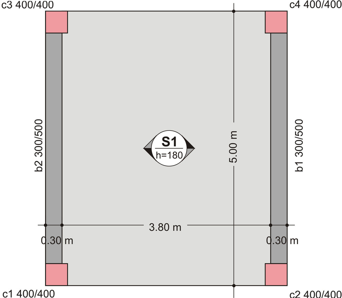
The carpenter’s formwork drawing regards the formation of the slab’s moulds
Behavior and reinforcement of one-way slab

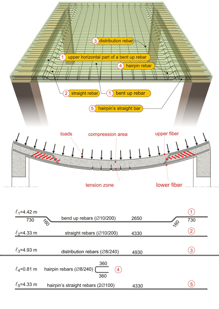
The installer’s formwork drawing regards the slab’s reinforcement
The slab of the above example has four types of reinforcement:
1st) primary reinforcement
In a one-way slab the need for reinforcement appears mainly in the span and towards the bending direction. The necessary bars are placed based on the amount of the calcu-lated required reinforcement. In this specific case the provided bars are Ø10/100. This means that Ø 10 rebars have been placed every [*]NoteThe reinforcement in slabs is calculated per 1m of width. In this specific example, in every 1 m (1000 mm) of slab width there are 1000/100=10 rebars. The Ø 10 rebar has a cross-sectional area of π*d2/4=π*1.02/4=78.5 mm2 and therefore, the total amount of reinforcement placed in 1m is 10bars*78.5=785 mm2. This value can be taken directly from table 3. 100 mm.
2nd) secondary reinforcement or distribution reinforcement
Apart from the primary reinforcement that is placed parallel to the deformation direction, there is also need for reinforcement in the secondary direction. In that direction, the placed rebars are Ø 8/240 which means that bars with a Ø 8 diameter have been placed every [*]NoteThe Ø 8 rebar has a cross-sectional area equal to π*82/4=50.3 mm2. The rebars placed in 1m are 1000/240=4.17 consequently, the total amount of secondary reinforcement is 4.17*50.3=210 mm2/m. This value can also be taken directly from table 3 in ½* Ø 8/120 240 mm.
3rd) free edge reinforcement
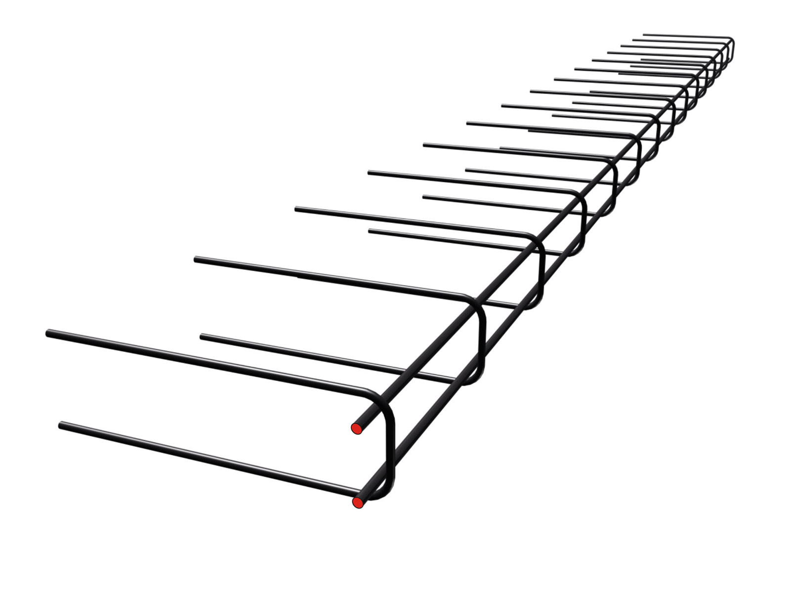
The free edges of slabs are more susceptible to stresses and therefore, hairpin reinforcement is placed in these areas. Its proper position is secured by means of two bars placed inside its corners.
Hairpin reinforcement is easily formed by a folded wire mesh (see and paragraph 2.6.1).
4th) support reinforcement
The minimum required reinforcement in the support areas is provided by two ways:
1st way: Half the span rebars i.e. Ø 10/200 are shaped with bends at their ends (in every two bars one is straight and one is bend-up). The other half span rebars are formed with a straight length. That way has been followed in this specific example.
2nd way: All span rebars i.e. Ø 10/100 are manufactured and implemented with a straight length while in the upper part of the support areas additional straight rebars are placed.
*√2= 110*1.4=160 mm")
Calculation of the bent-up part of a rebar If the slab’s thickness is 180 mm, then the bent-up part will have a length equal to: (180-35-35)*√2= 110*1.4=160 mm
For an effortless and economical implementation, when using straight-length rebars it is obliga-tory to use industrial wire fabric reinforcement as shown in the following figure.
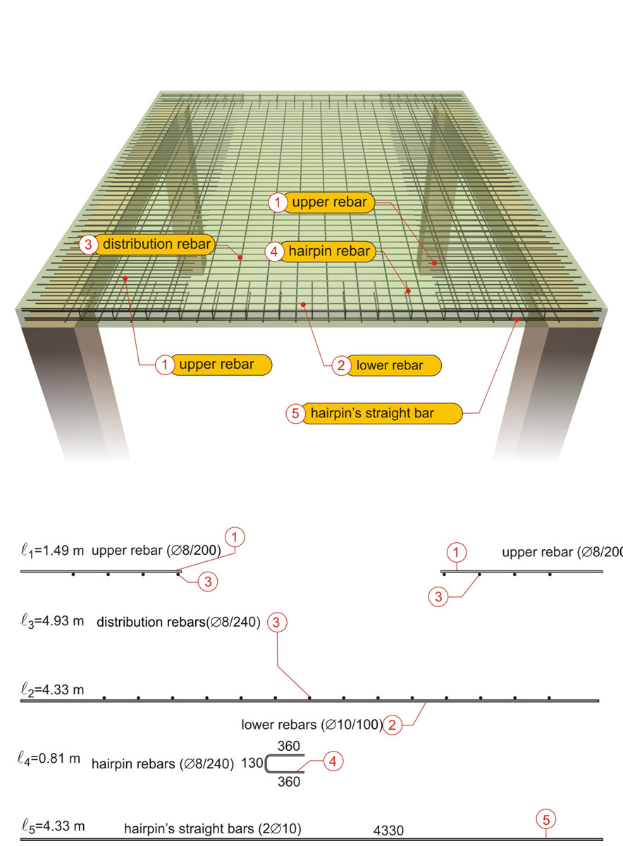
Reinforcing the one-way slab of the above example by means of straight-length bars “project: slabs15”
In case a slab is reinforced only with straight-length bars which, as a rule, means reinforcement with wire fabrics, the installer’s formwork drawing is shown in the image below.

The installer’s formwork drawing of a one-way slab, reinforced with straight-length bars
